Microwave Transmission-Line Impedance Data

A compendium of data for computing the characteristic impedance of transmission lines based on physical dimensions, this book covers both conventional structures and unusual geometries.
Two of the four transmission lines treated in this chapter have few microwave applications because of excessive losses occasioned by radiation: their presence in a book devoted to microwave topics may therefore be questioned. However, they have been included (see Sections 2.4 and 2.5) because of the close "family relationship" which exists between all four lines described, and also because the two "interlopers" are direct ancestors of the microstrip transmission line (see Section 3.6), which is now of such great importance in microwave miniaturization and integrated circuit applications.
Strictly speaking, the elliptic coaxial line should be included in this chapter, since it is the basic form from which the coaxial line and its relatives are derived. However, since its conductors are not circular in cross-section, and since it is of little practical importance, it has been included in Chapter 5, under the heading of "lines of unusual cross-section."
Following the sequential order of description outlined in Section 1.3, the most symmetrical configuration of conductors is treated first.
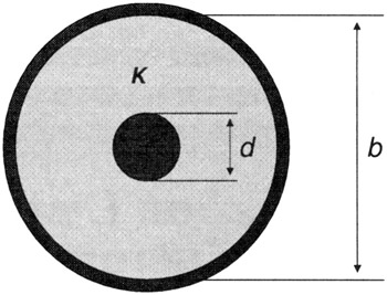
As is implied by the name, the two cylindrical conductors which constitute this line are located coaxially, one within the other, as shown in cross-section in Fig. 2-1. The symbolism used here for the dimensional parameters departs from that in common use (in which the outer diameter is 2 b, the inner diameter, 2 a); this is simply for the sake of consistency with the notation used in the remainder of the book.