Microwave Transmission-Line Impedance Data

A compendium of data for computing the characteristic impedance of transmission lines based on physical dimensions, this book covers both conventional structures and unusual geometries.
This structure, shown in cross-section in Fig. 3-5, was first proposed for use as a transmission line by Barrett and Barnes [23]. Hitherto, it has been almost universally known as "stripline," since it was the first form of planar strip transmission line to achieve widespread use in microwave technology. However, in view of the now equally extensive use of "micro-" and "High-Q-" striplines it has become necessary to prefix the qualifying term "triplate."
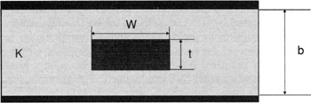
It is readily apparent that the triplate line can be derived from the rectangular coaxial line by the simple step of letting W become infinite.
Practical stripline circuits are frequently constructed from copper-clad printed-circuit boards, with the result that the centre-conductor thickness t is usually very small in comparison with the other transverse dimensions of the line. In any relevant mathematical analyses it is therefore often reasonable to assume that t = 0, since this leads to considerable simplification of the problem.
Both situations, i.e. t=0, and t>0, are discussed in the sections which follow.
As in coaxial line systems, it is usually necessary or desirable to ensure the non-propagation of higher-order (non-TEM) modes, and this can be done by ensuring that b < ?/2. If information about these higher modes is required, it can be deduced from...