Microwave Transmission-Line Impedance Data

A compendium of data for computing the characteristic impedance of transmission lines based on physical dimensions, this book covers both conventional structures and unusual geometries.
The widespread success of microstrip circuitry has led to fairly intensive investigation of similar line structures, and at the time of writing several different, but related, versions are known, but as yet unproven. Hence, for purposes of reference, it has been thought desirable to include a few of the more promising of these, even though little detailed information is available at present.
Two versions of this have been proposed, both of which are illustrated in cross-section in Fig. 3-15. As is apparent, they both incorporate a strip conductor supported upon a thin dielectric substrate, the under-surface of which is unmetallized. The two structures differ only in the shape of the surrounding conductor, which is circular in one case and rectangular in the other.
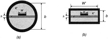
The circular version was proposed, and put to practical use, by Okean [65]. Under the classification system adopted in this book, this line should perhaps more properly be treated in the next chapter, but its obvious close relationship to "ordinary" microstrip is sufficient reason for its inclusion here. But see Section 4.6 for a similar transmission line, which constitutes the "limiting case" of the one at present under discussion.
An exact analysis of this structure is not known, but under the pseudo-TEM mode assumption, the characteristic impedance is given by
where ? e is the effective dielectric constant of the structure given by:
C is the...