9.2 FILTER SPECIFICATIONS
Before a filter can be designed, a set of filter specifications must be defined. For example, suppose that we would like to design a low-pass filter with a cutoff frequency ? c. The frequency response of an ideal low-pass filter with linear phase and a cutoff frequency ? c is
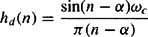
which has a unit sample response
Because this filter is unrealizable (noncausal and unstable), it is necessary to relax the ideal constraints on the frequency response and allow some deviation from the ideal response. The specifications for a low-pass filter will typically have the form
as illustrated in Fig. 9-1. Thus, the specifications include the passband cutoff frequency, ? p, the stopband cutoff frequency, ? s, the passband deviation, ? p, and the stopband deviation, ? s. The passband and stopband deviations
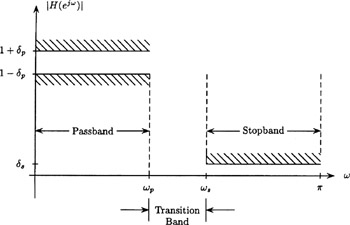 Figure 9-1: Filter specifications for a low-pass filter.
 are often given in decibels (dB) as follows:
and
The interval [ ? p, ? s] is called the transition band.
Once the filter specifications have been defined, the next step is to design a filter that meets these specifications.

 TABLE OF CONTENTS