Secrets of 5-Axis Machining
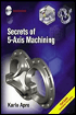
Unbiased and no-nonsense, this to-the-point book demystifies 5-axis machining, and will bring it within the reach of anyone who is interested in using this technology to its full potential.
 TABLE OF CONTENTS
 Nesting positions are widely used for positioning work. These positions, shown in Figure 2-19, are temporary Active Coordinate Systems and are typically set in relation to different faces of the part or fixture face, tooling ball, or dowel pin.

The advantage of using these Local Coordinate Systems is that you can easily follow the program on the controller s display screen because the absolute values shown there will reflect the values relative to each locally-nested position. Z+1.000, for example will be 1.000 (inch) above the part face.
Despite the fact that CAM systems all use different naming conventions for their coordinate systems, they all handle the local coordinate system in a similar way. Some of the names used by CAD/CAM systems include: Part Datum, Active Coordinate System, Local Coordinate System, System View, and Tool Plane with an Origin.
The disadvantage of using a number of different local coordinate systems is the potential for misalignment when picking up these positions manually with a dial indicator. Many programmers use only one coordinate system for 5-axis work. They use the Machine Rotary Zero Point (MRZP) as the part datum and let either the CAM system or the machine s controller calculate the special movements necessary. If a part is placed in the same position in the CAM and in the machine, the CAM is very capable of generating the correct code.
The advantage...