Secrets of 5-Axis Machining

Unbiased and no-nonsense, this to-the-point book demystifies 5-axis machining, and will bring it within the reach of anyone who is interested in using this technology to its full potential.
 TABLE OF CONTENTS
 First, make sure that the machine head is in a perfect vertical orientation by touching the machine s table with a dial indicator, then rotating the indicator. The indicator should read zero around the whole circle as shown in Figure 2-35.
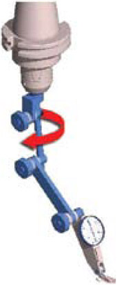
Figure 2-35: Indicating vertical position.
Place a 1.000 diameter dowel pin into the master tool holder with a known Gage Length (GL).
Touch the dial indicator plunger as shown in Figure 2-36. A flat attachment helps here. Set the indicator to zero and record the Z value on the controller s screen. Let s call this value Z maximum.
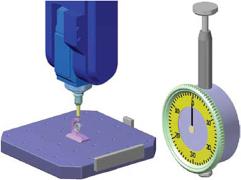
Figure 2-36: Touching the dial indicator plunger is eased by having a wide, flat top on the plunger.
Do not move the machine on the X axis. Move only on the Y and Z axes. Move to a safe point on the Z axis, and rotate the A axis through 90 degrees into a horizontal orientation. Next, move on the Y axis in the plus and on the Z axis in the minus directions until you get to the position shown in Figure 2-37.

Figure 2-37: Z minimum position.
Record this Z value on your controller s screen and let s call this Z minimum.
You should have the following values handy:
Z maximum
Z minimum
GL - Gage Length
R - Dowel pin radius = .5000
Formula to calculate Pivot Distance:
PD = Z max Z min GL + R
This...