Successful Instrumentation and Control Systems Design
The "Standards and Practices" chapter in Part II described basic wiring techniques. Topics such as signal sinking versus sourcing, wire numbering techniques, and other topics pertinent to the art of wiring a control system were discussed. The NFPA 79 standard was discussed as well. This chapter is about the practical aspects of generating a set of wiring drawings suitable for construction and plant maintenance.
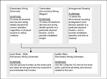
What constitutes the I&C wiring set of deliverables? Figure 142 describes the relationships among the different types of drawings.
Why three different types of drawings? The answer: each set has its purpose. The three are needed to cover three different perspectives.
First, the fabricator needs guidance in building the cabinetry panels. The fabrication function may be performed by a vendor or the constructor. While this may not be wiring per se, it is so closely tied to the wiring task as to be indistinguishable. The design of the enclosure must accommodate the wiring and the wiring components (see Figure 143).
Next, the constructor needs to be provided for. A set of drawings should be generated that presents the wiring information from the perspective of the wiring installer. An installer working in a junction box, for example, needs wiring information only for that box, not for the whole circuit. Only information for the point-to-point wiring that must be done in that panel is needed. This kind of point-to-point wiring drawing is called a connection diagram (see Figure 144).