Circuit Analysis II with MATLAB Computing and Simulink/SimPowerSystems Modeling

9.5: Establishing Polarity Markings

9.5 Establishing Polarity Markings

In our previous discussion and in Examples 9.1 and 9.2, the polarity markings (dots) were given. There are cases, however, when these are not known. The following method is generally used to establish the polarity marking in accordance with the dot convention.

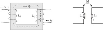
Consider the transformer and its circuit symbol shown in Figure 9.13.


Figure 9.13: Establishing polarity markings

We recall that the direction of the flux ? can be found by the right-hand rule which states that if the fingers of the right hand encircle a winding in the direction of the current, the thumb indicates the direction of the flux. Let us place a dot at the upper end of L 1 and assume that the current i 1 enters the top end thereby producing a flux in the clockwise direction shown. Next, we want the current in L 2 to enter the end which will produce a flux in the same direction, in this case, clockwise. This will be accomplished if the current i 2 in L 2 enters the lower end as shown and thus we place a dot at that end.

Example 9.3

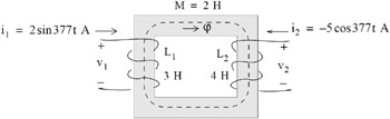
For the transformer shown in Figure 9.14, find v 1 and v 2.


Figure 9.14: Network for Example 9.3

Solution:

Let us first establish the dot positions as discussed above. Since the current i 2 has a negative sign, it leaves the upper terminal, or equivalently, enters the lower terminal...

UNLIMITED FREE
ACCESS
TO THE WORLD'S BEST IDEAS

SUBMIT
Already a GlobalSpec user? Log in.

This is embarrasing...

An error occurred while processing the form. Please try again in a few minutes.

Customize Your GlobalSpec Experience

Category: Rectifiers
Finish!
Privacy Policy

This is embarrasing...

An error occurred while processing the form. Please try again in a few minutes.