Circuit Analysis II with MATLAB Computing and Simulink/SimPowerSystems Modeling
A linear transformer is a four-terminal device in which the voltages and currents in the primary coils are linearly related.
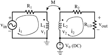
The transformer shown in figure 9.22 a linear transformer. This transformer contains a voltage source in the primary, a load resistor in the secondary, and the resistors R 1 and R 2 represent the resistances of the primary and secondary coils respectively. Moreover, the primary is referenced to directly to ground, but the secondary is referenced to a DC voltage source V 0 and thus it is said that the secondary of the transformer has a DC isolation.
Application of KVL around the primary and secondary circuits yields the loop equations
* The mutual inductance terms
and
have a negative sign since the current i 2 is leaving the dotted terminal of the transformer secondary.
and we see that the instantaneous values of the voltages and the currents are not affected by the presence of the DC voltage source V 0 since we would have obtained the same equations had we let V 0=0 .
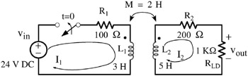
For the transformer shown in Figure 9.23, find the total response of i 2 for t>0 given that i 1(0 ?)=i 2(0 ?)=0. Use MATLAB to sketch i 2 for 0 ?t ?5 s.
Solution:
The total response consists of the...