Power Supplies for LED Driving
Including detailed examples of what works and why, this practical, hands-on book covers the design trade-offs involved in LED driving applications, from low-power to UB-LEDs and beyond.
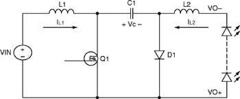
A boost-buck converter is a single-switch converter, which consists of a cascade of a boost converter followed by a buck converter. The power train of typical boost-buck circuit topology (used as an LED driver) is shown in Figure 7.1.
The converter has many advantages:
The converter can both boost and buck the input voltage. Thus, it is ideal for cases where the output LED string voltage can be either above or below the input voltage during operation. This condition is most common in automotive applications, or when a customer wants a single driver design to cover a wide range of voltage supply and load conditions.
The converter has inductors on both the input and output sides. Operating both stages in continuous conduction mode (CCM) will enable continuous currents in both inductors with low current ripple, which would greatly reduce the filter capacitor requirements at both input and output. Continuous input current would also help greatly in meeting conducted EMI standards at the input.
All the switching nodes in the circuit are isolated between the two inductors. The input and output nodes are relatively quiet. This will minimize the radiated EMI from the converter. With proper layout and design, the converter can easily meet radiated EMI standards.
One of the advantages of the boost-buck converter is the capacitive isolation. The failure of the switching transistor will short the input and not affect the output. Thus, the LEDs are protected from failure of the MOSFET.