Parity Checkers and Generators Information
 Parity checkers and generators detect errors in binary data streams. Parity-checking devices combine a generator and checker into an integrated circuit (IC) package.
Parity
Parity is one of the simplest error-detection methods for checking binary data streams. Parity checkers contain transmission and receiving ends. They divide binary streams into sections of 7 or 8 bits and generate a parity bit at the transmission end. A second parity bit is then generated at the receiving end; if the transmission bit and receiving bit match, the data is verified as accurate.
Even/Odd Parity
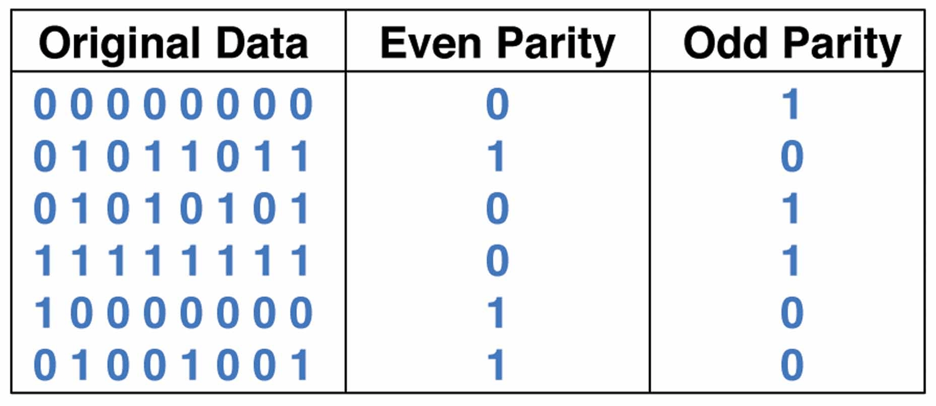
Parity essentially measures the sum of the one bits (as opposed to zero, the other binary value) contained in the data and is classified as even or odd depending on these sums. In even parity, the sum of the ones plus the parity bit must be even, while in odd parity the sum must be odd. For example, if a device checks the data stream 0111000 for even parity, the parity bit must be 1 if the data is accurate; in this case the sum of the ones and parity bit is four, an even number.
The table below illustrates using parity bits to adjust data streams depending on whether parity is even or odd.

Image credit: University of London Birkbeck
Parity is a limited and somewhat simplistic method for checking binary data. It is prone to errors and shortcomings due to its status as a "pass-fail" sum-based method for error detection. For example, if a digit is switched during transmission parity can flag the data stream as "bad" but is unable to identify which bit caused the error.
Additionally, if two bits are switched, a parity checker would judge the data stream to be accurate because it can only gage whether the stream's sum of one digits is even or odd. Because adding two digits to any integer renders its parity identical, parity checkers are not reliable if two or four digits are switched in the same stream.
Applying Parity
Parity checkers are common in binary communications systems. They are also integrated into networked systems and computers, where they are used to test memory storage devices in real-time.
Errors and Causes
Parity errors may have "hard" or "soft" causes. Most errors are classified as soft errors, meaning they are caused by environmental factors such as electrostatic discharge (ESD) or electromagnetic interference (EMI). These conditions can unexpectedly change a memory cell's electrical state or interfere with its read/write functions. Soft errors typically occur only once and can be caused by nearby power cables, generators, lighting systems, and radiation issuing from solar flares or nuclear power systems.
Hard parity errors are caused by physical malfunctions in memory devices. A malformed memory cell may be unable to hold a charge or be more vulnerable to soft errors. Hard errors may also occur outside of healthy memory cells in the read/write circuity, causing a parity error in transmission. Because hard errors are due to physical anomalies, they recur each time the device is used. This error type is often caused by extreme temperatures, poor installation practices, ungrounded power surges, ESD, manufacturing errors, and component incompatibility.
Design and operation of a parity checker, showing the interaction between generation and check functions.
Image credit: T4planet
Logic Families
A parity checker's logic family technology is one of its more important specifications. Some examples include:
- Transistor-transistor logic (TTL) and related technologies such as Fairchild advanced Schottky TTL (FAST) use transistors as digital switches.
- Emitter coupled logic (ECL) uses transistors to steer current through gates that compute logical functions.
- Complementary metal-oxide semiconductor (CMOS) uses a combination of p-type and n-type metal-oxide-semiconductor field effect transistors (MOSFETs) to implement logic gates and other digital circuits.
- Bipolar CMOS (BiCMOS) is a silicon-germanium technology that combines the high speed of bipolar TTL with the low power consumption of CMOS.
Other logic families for parity checkers and generators include cross-bar switch technology (CBT), gallium arsenide (GaAs), integrated injection logic (I2L), silicon on sapphire (SOS), and gunning with transceiver logic (GTL).
Standards
Parity checkers may be designed and manufactured according to various published standards, including:
SMD 5962-87543—Digital bipolar parity checker
IETF RFC 5170—Low density parity check (LDPC) staircase and triangle forward error correction (FEC) schemes
Other parity-related standards can be found on Engineering360's standards page.
References
The Math Forum—Parity Checking
