Practical Optical System Layout and Use of Stock Lenses

Chapter 4: System Limits: Performance and Configuration

4.1 Introduction

It is the intent of this chapter to briefly outline some limits to which all optical systems must conform. These are: (1) limits of performance or resolution, (2) limits on throughput, and (3) limits on the relationships between beam angles and sizes. In the initial stages of system layout it is essential that these limits be known and harmonized with what is expected of the optical system. Occasionally this first step simply proves that "it can't be done." But even a negative result like this can be worthwhile if it avoids a waste of time spent on the physically impossible.

4.2 The Diffraction Limit

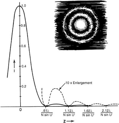
The image of a point source, formed by a perfect optical system with a uniformly transmitting circular aperture, is a diffraction pattern which consists of a circular central bright patch, called the Airy disk, surrounded by alternating dark and light concentric rings. The Airy disk contains 84 percent of the energy in the image. The first dark ring has a diameter given by

(4.1)

where ? is the wavelength and NA is the numerical aperture of the imaging cone of light (NA = n sin u). The peak illumination in the first bright ring is only 1.7 percent of the peak illumination in the Airy disk, and the illumination level in the other rings falls off quite rapidly. Figures 4.1 and 4.2 describe the diffraction pattern.


Figure 4.1: The diffraction pattern: the image of a point formed by a...

UNLIMITED FREE
ACCESS
TO THE WORLD'S BEST IDEAS

SUBMIT
Already a GlobalSpec user? Log in.

This is embarrasing...

An error occurred while processing the form. Please try again in a few minutes.

Customize Your GlobalSpec Experience

Category: Photodiodes
Finish!
Privacy Policy

This is embarrasing...

An error occurred while processing the form. Please try again in a few minutes.