Radio Receiver Design

This reference focuses on understanding and designing radio receivers and systems, presenting the characteristics of individual receiver components and their interaction in cascade.
 TABLE OF CONTENTS
 Purity lives and derives its life solely from the spirit of God.
-David Hare (1917-1992)
Oscillators play an important part in the ultimate performance of receivers. In this chapter, we will examine oscillator phase noise, frequency accuracy, drift and their cumulative effects on receiver performance.
Figure 4-1 shows some of the characteristics of an ideal oscillator. The time-domain plot of an ideal oscillator is a mathematically perfect sine wave [see Figure 4-1(a)]. There is no noise present on the signal. The period, defined as the time between zero crossings, is 1/ f 0 where f 0 is the frequency.
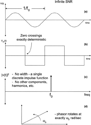
Figure 4-1(b) shows the zero crossings of the waveform are exactly deterministic: we know precisely when the waveform will cross zero.
Figure 4-1(c) shows that the single-sided Fourier spectrum of a perfect oscillator is a single, discrete impulse function with zero width. The spectrum contains no other discrete components such as harmonics and sampling sidebands. The signal has an infinite signal-to-noise ratio. The ideal oscillator is always exactly on the desired frequency over time, temperature, power supply variations, and so on.
Figure 4-1(d) shows the phasor representation of an ideal oscillator. A single phasor rotates counterclockwise about the origin at an angular frequency of ? 0.
Actual oscillators are not ideal. Figure 4-2 shows the less-than-ideal properties of one such oscillator.