Radio Receiver Design
This reference focuses on understanding and designing radio receivers and systems, presenting the characteristics of individual receiver components and their interaction in cascade.
 TABLE OF CONTENTS
 What are you able to build with your blocks? Castles and palaces, temples and docks.
-R.L.S.
This chapter discusses how filters, amplifier noise, amplifier linearity, mixers, oscillators and transmission lines interact in cascade and how to distribute the gain along the cascade. Numerous examples are supplied to indicate the advantages and disadvantages with each system.
The receiving system of Figure 7-1 contains an antenna, a demodulator and the electronics between the two. The antenna port presents the receiver with different signals at different frequencies, with varying power levels and different types of modulation. The demodulator expects its input signal to always be centered at one frequency, the intermediate frequency (IF), ,and that its input signal to be at a particular power level.
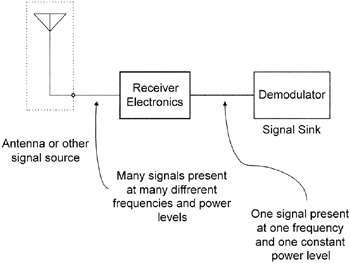
The signal of interest is converted from its on-the-air frequency to the IF. Further, the gain of the receiver electronics is adjusted so the demodulator always sees a constant power level. This task is complicated by oscillator drift (both in the transmitter and receiver), phase noise, interfering signals, multipath and other difficulties.
Figure 7-2 shows some of the specifications of the antenna (signal source) and the signal sink (demodulator).
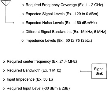
The signal source provides signals with the following characteristics:
different center frequencies,
different bandwidths,
different signal power levels,
a noise floor that changes with frequency,
a nominal impedance environment.