Depth Gages Information
Last revised: January 10, 2025
Depth gages are used to measure the depth of holes, cavities, and other component features. They are available in various configurations, depending on the specific application. Depth gage categories include:
- dial depth gages
- digital depth gages
- depth micrometers
- thread depth gages
- flush-pin gages
- depth rules
- combination depth angle gages
- Vernier depth gages
Types of Depth Gages
- Thread depth gages measure the depth of the thread surface in a hole.
- Flush-pin depth gages are go/no-go functional gages that rapidly assess the depth of the opening.
- Depth rules allow quick assessment. Typically, depth rules are used in applications where precision is not a high priority.
- Combination depth angle gages indicate the depth and orientation of a hole.
- Vernier depth gages have graduations engraved or printed onto a surface (linear or drum). The main scale provides an indication of the gaged dimension to a standard precision level (e.g., tenths). The Vernier scale also allows an increased level of precision (e.g., thousandths).
Specifications
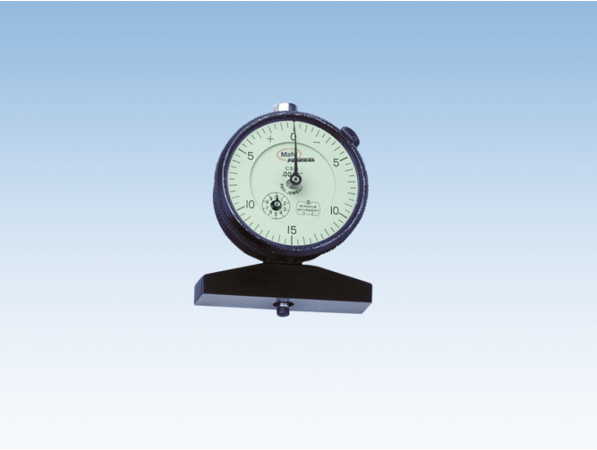
Dial depth gages display data with a pointer or needle mounted in a graduated disc-dial. The dial indicates dimensions and positions around or from a reference point. Examples of depth gage graduations are 10-0-10, 45-0-45, 4-0-4, 50-0-50. Dial display design options include clockwise and counter-clockwise rotation, one or multi-revolution capabilities, and an analog amplifier. With dial depth gages, the analog amplifier provides a remote, electronic equivalent to the mechanical display.
Features
Digital depth gages present meteorological data in numeric or alphanumeric form. They often have data output capabilities that use serial or other formats. Digital readouts are precise digital displays that are integrated into dimensional depth gages. Depth micrometers are another type of depth gage with a digital option. Typically, depth micrometers are used for precision dimensional gaging. They are made of a ground spindle and an anvil that is mounted in a tee-shaped frame. Micrometer depth gages are also available in both scale and dial varieties.
Depth Gages FAQs
How do different types of depth gages vary in their accuracy and precision?
When considering the accuracy and precision of different types of depth gages, several factors come into play. Here is a structured overview based on the information available:
Types of Depth Gages
Digital Depth Gages: These gages present data in numeric or alphanumeric form and often have data output capabilities. They are known for their precision in displaying measurements digitally.
Depth Micrometers: These are used for precision dimensional gaging and are available in both digital and dial varieties. They consist of a ground spindle and an anvil mounted in a tee-shaped frame, providing high precision.
Accuracy and Precision Factors
Measurement Precision: In the field of machine building and maintenance, measurements typically require precision on the order of 0.001 inch, or one thousandth of an inch. Instruments like dial or vernier calipers, micrometers, and dial indicators are commonly used for such precision.
Sensor Technology: High-accuracy gaging units may use precision linear encoders or laser-based interferometers. Linear encoders generally provide uncertainties of 10 micro-inches (0.25 microns), while laser-based units can achieve results in the 2-3 micro-inch range (0.05-0.075 microns).
Considerations for Use
Abbe Offset Errors: Dial calipers may be subject to Abbe offset errors due to the measurement scale being offset from the measurement axis. In contrast, micrometers, where the measurement barrel is in line with the measurement axis, are not subject to these errors.
What are the advantages of using laser-based interferometers in depth gages?
Laser-based interferometers offer several advantages when used in depth gages, particularly in terms of accuracy and precision. Here are some key benefits:
High Precision: Laser-based interferometers can achieve very high levels of precision, with results in the range of 2-3 micro-inches (0.05-0.075 microns). This makes them suitable for applications requiring extremely fine measurements.
Reduced Measurement Uncertainty: Compared to other sensor technologies like precision linear encoders, which provide uncertainties of 10 micro-inches (0.25 microns), laser-based interferometers offer lower measurement uncertainties, enhancing the reliability of the measurements.
Extended Measurement Range: Laser-based instruments can provide direct readings over larger ranges, well up to 64 inches (1,635 mm) in length, which is beneficial for applications requiring measurements over extended distances.
How do Abbe offset errors affect measurement accuracy?
Abbe offset errors can significantly affect measurement accuracy, particularly in instruments where the measurement scale is offset from the measurement axis. Here's how these errors impact accuracy.
Nature of Abbe Offset Errors
Abbe offset errors occur when there is a misalignment between the measurement axis and the scale of the measuring instrument. This misalignment can introduce errors in the measurement, as the actual measurement path is not aligned with the scale used to read the measurement.
Impact on Measurement Instruments
Instruments like dial calipers are susceptible to Abbe offset errors because their measurement scale is offset from the measurement axis. This can lead to inaccuracies in the readings, as the offset introduces a discrepancy between the actual dimension being measured and the reading on the scale.
Avoidance in Certain Instruments
In contrast, micrometers are designed with the measurement barrel in line with the measurement axis, which eliminates the potential for Abbe offset errors. This alignment ensures that the measurement path and the scale are congruent, leading to more accurate measurements.
These errors highlight the importance of instrument design in ensuring measurement accuracy, particularly in precision applications.
How do the different depth gages handle measurement errors?
When it comes to handling measurement errors, different types of depth gages employ various methods and technologies to minimize inaccuracies and enhance precision.
Design and Alignment
Abbe Offset Errors: Instruments like dial calipers are susceptible to Abbe offset errors due to the misalignment between the measurement axis and the scale. This can introduce discrepancies in measurements. In contrast, micrometers are designed with the measurement barrel in line with the measurement axis, effectively eliminating Abbe offset errors and ensuring more accurate readings.
Sensor Technology
Precision Linear Encoders: These are used in high-accuracy gaging units and generally provide uncertainties of 10 micro-inches (0.25 microns). They are suitable for applications where moderate precision is acceptable.
Laser-Based Interferometers: These offer superior precision with measurement uncertainties in the range of 2-3 micro-inches (0.05-0.075 microns). This technology is particularly beneficial for applications requiring extremely fine measurements and reduced measurement uncertainty.
Digital Readouts
Digital Depth Gages: These gages present data in numeric or alphanumeric form, often with data output capabilities. The digital display provides precise readings, reducing the likelihood of human error in interpreting measurements.
Calibration and Standards
Calibration is crucial for ensuring the accuracy of depth gages. It involves comparing the instrument's value to a known standard of higher order, establishing its accuracy. This process helps in maintaining the reliability of measurements by aligning them with recognized standards.
These methods and technologies highlight the importance of instrument design, sensor technology, and calibration in handling measurement errors effectively.
What is the calibration process for depth gages?
The calibration process for depth gages is crucial to ensure their accuracy and reliability in measurements. Here is an overview based on the information available:
Definition of Calibration
Calibration is the process of comparing a measuring instrument's value to a known standard of higher order. This comparison establishes the accuracy of the instrument, ensuring that it provides correct measurements relative to a recognized standard.
Importance of Calibration
Calibration is essential in maintaining the reliability of measurements. It aligns the instrument's readings with recognized standards, which is particularly important in fields requiring high precision, such as machine building and maintenance.
Calibration Standards
The field of metrology generally requires that instruments of measurement have an accuracy of 1/10 of the desired precision. For example, to achieve a precision of 0.001 inch, the calibration process would involve using standards that ensure the instrument's accuracy to 0.0001 inch.
Unfortunately, the documents do not provide detailed procedural steps for calibrating depth gages specifically. However, the general principles of calibration outlined above are applicable to depth gages as well.
What are the common challenges in calibrating depth gages?
Calibrating depth gages can present several challenges, which are important to address to ensure accurate and reliable measurements. Here are some common challenges based on the information available:
Proper alignment is crucial when calibrating depth gages. Misalignment can lead to cosine errors, which occur when the part being measured is tilted. This can introduce significant measurement errors, especially in precision applications.
Using a master that matches the material and shape of the part being measured is important to minimize penetration effects. This ensures that the calibration is accurate and reflective of the actual measurement conditions.
The gaging force used during calibration should match the force used in actual measurements. Variations in gaging force can lead to discrepancies between the calibrated values and the actual measurements.
Changes in environmental conditions, such as temperature, can affect the calibration process. It is important to verify calibration whenever there are changes in probe orientation or environmental temperature to maintain accuracy.
Calibration can be labor-intensive, especially when using short-range comparators, which require more time and effort compared to direct reading units. This can be a challenge in terms of both time and cost efficiency.
These challenges highlight the importance of careful planning and execution in the calibration process to ensure that depth gages provide accurate and reliable measurements.
What are the best practices for ensuring proper alignment during calibration?
Ensuring proper alignment during the calibration of depth gages is crucial to minimize measurement errors such as cosine errors.
Ensure that the reference figures of the part being measured are properly aligned. This helps in maintaining the correct orientation and reduces the likelihood of errors due to misalignment.
During calibration, rotate the part while searching for a minimum reading. This practice helps in identifying the correct alignment by minimizing the distance between the measurement surfaces, thus reducing cosine errors.
Ensure that the gaging force used during calibration matches the force used in actual measurements. Consistency in gaging force helps in maintaining the accuracy of the calibration process.
Be mindful of environmental factors such as temperature changes, which can affect calibration. Verify calibration whenever there are changes in probe orientation or environmental temperature to maintain accuracy.
Depth Gages Media Gallery
References
GlobalSpec—Metrology Investments Increase Manufacturing Accuracy and Efficiency, Reduces Costs
GlobalSpec—Machinery Vibration: Alignment
Image credit: