4.6 I/O addresses
The PLC has to be able to identify each particular input and output. It does this by allocating addresses to each input and output. With a small
PLC this is likely to be just a number, prefixed by a letter to indicate whether it is an input or an output. Thus for the Mitsubishi PLC we might have inputs with addresses X400, X401, X402, etc., and outputs with addresses Y430, Y431, Y432, etc., the X indicating an input and the Y an output. Toshiba use a similar system.
With larger PLCs having several racks of input and output channels, the racks are numbered. With the Allen-Bradley PLC-5, the rack containing the processor is given the number 0 and the addresses of the other racks are numbered 1, 2, 3, etc. according to how set-up switches are set. Each rack can have a number of modules and each one deals with a number of inputs and/or outputs. Thus addresses can be of the form shown in Figure 4.31. For example, we might have an input with address I:012/03. This would indicate an input, rack 01, module 2 and terminal 03.
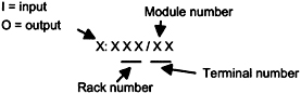 Figure 4.31: Allen-Bradley PLC-5 addressing
 With the Siemens SIMATIC S5, the inputs and outputs are arranged in groups of 8. Each 8 group is termed a byte and each input or output within an 8 is termed a bit. The inputs and outputs thus have their addresses in terms of the byte and bit numbers, effectively giving a...