Microwave Measurements, 3rd edition
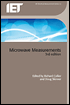
P. R. Young
Scattering parameters or scattering coefficients are fundamental to the design, analysis and measurement of all microwave and millimetre-wave circuits and systems. Scattering parameters define the forward and reverse wave amplitudes at the inputs and outputs of a network. Microwave networks take on various forms and can be as simple as a shunt capacitor or as complicated as a complete system. Common microwave networks are one-, two-, three- or four-port devices.
The definition of a scattering parameter is intrinsically linked to the form of transmission medium used at the ports of the network. Transmission lines and waveguides come in four distinct classes: (1) transverse electromagnetic (TEM), which includes coaxial lines and parallel pairs; (2) quasi-TEM lines, such as microstrip and coplanar waveguide (CPW); (3) transverse electric (TE) and transverse magnetic (TM) waveguides, such as rectangular waveguide; and (4) hybrid waveguides, which include dielectric guides and most lossy transmission lines and waveguides.
For simplicity, the one-port scattering parameter or reflection coefficient will be defined first for TEM lines before the more complicated multi-port and waveguide networks are analysed.
Consider a simple two-conductor transmission line, such as a coaxial cable or parallel pair. These types of transmission lines support TEM waves allowing the wave transmission to be expressed purely in terms of voltage between the conductors and the current flowing through the conductors. If the line is terminated by a load Z (Figure 2.1), which is not perfectly matched with the transmission line, then...