Circuit Analysis II with MATLAB Applications

Designed for use in a second course in circuit analysis, this text engages a full spectrum of circuit analysis related subjects ranging from the most abstract to the most practical.
 TABLE OF CONTENTS
 Let us consider the series RLC circuit of Figure 1.1 where the initial conditions are i L(0) = I 0, v C(0) = V 0, and u 0( t) is the unit step function. [*] We want to find an expression for the current i( t) for t > 0.
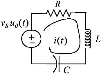
For this circuit

and by differentiation
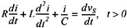
To find the forced response, we must first specify the nature of the excitation v S, that is, DC or AC. If v S is DC ( v S=constant), the right side of (1.1) will be zero and thus the forced response component i f = 0. If v S is AC ( v S = Vcos( ? t + ?), the right side of (1.1) will be another sinusoid and therefore i f = Icos( ? t + ?). Since in this section we are concerned with DC excitations, the right side will be zero and thus the total response will be just the natural response.
The natural response is found from the homogeneous equation of (1.1), that is,

The characteristic equation of (1.2) is
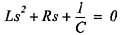
or
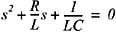
from which

We will use the following notations:

where the subscript s stands for series circuit. Then, we can express (1.3) as

or

Case I: