Computer Arithmetic Algorithms, Second Edition
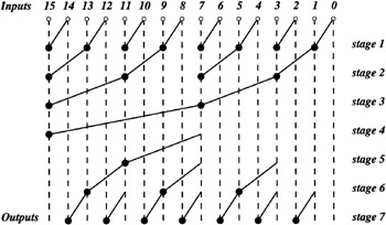
The adder shown in Figure 5.8 may be viewed as a parallel prefix circuit. A parallel prefix circuit is a combinational circuit with n inputs x 1, x 2, , x n producing the outputs x 1 , x 2 ? x 1 , , x n ? x n ?1 ? ? x 1, where ? is an associative binary operation. The first stage of the adder in Figure 5.8 generates the individual P i and G i signals. The remaining stages constitute the parallel prefix circuit with the fundamental carry operation serving as the ? associative binary operation. This part of the adder tree can be designed in many different ways. The particular way this part is implemented within the 16-bit Brent-Kung adder [2] in Figure 5.8 is shown in Figure 5.9. The bullets implement the fundamental carry operation while the empty circles at the top generate the individual P i and G i signals. Note that Figure 5.8 which generates G 15:0 shows only the top four stages of the complete parallel prefix graph in Figure 5.9 which uses seven stages to also generate all the intermediate carries G i :0 ( i =14, 13, , 1).
The number of stages and consequently, the total delay of the adder, can be reduced by modifying the structure of the parallel prefix...