Electrical Engineering Problems and Solutions, Eighth Ed

This companion volume to Electrical Engineering License Review covers 100% of the main book's end-of-chapter problems with detailed step-by-step solutions.
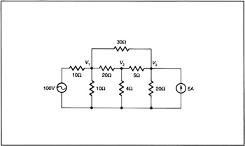
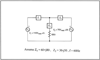
Determine the node voltages, V1, V2, and V3 by setting up the proper nodal equations in matrix form, manipulating the matrices to form the matrix solution for the voltages.
SOLUTION
To simplify the equations we may first replace the voltage source with its series resistance with a Norton equivalent circuit.
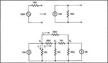
Note that the 10 ? resistor from the source is now in parallel with the 10 ? resistor of the network, making it effectively a 5 ? parallel branch.
The nodal equations are:
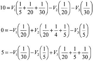
One would normally solve these equations by use of Cramer's rule; however the problem specifies the use of matrices.
This is in matrix form:
[ I] = [ Y][ V]
Where:
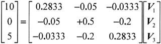
The matrix solution is:
[ V] = [ Y ?1][ I]
Where:
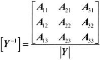
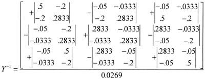
Where A ij = Signed minor o Y ij (cofactor)
(Reference: Lipshutz: Theory and Problems of Linear Algerbra. Schaum's Outline Series, McGraw-Hill, Chapter 8.) and ? Y ? is the determinant of the Y matrix.
Y = 0.0269
So
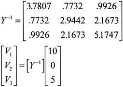
Multiplying row by column:
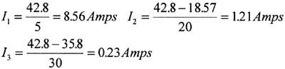
V 1 = 10(3.7807) + 0(0.7732) + 5(0.9926) = 42.77 volts
V 2 = 10(0.7732) + 0(2.9442) + 5(2.1673) = 18.57 volts
V 3 = 10(0.9926) + 0(2.1673) + 5(5.1747) = 35.80 volts
Check node no. 1
For 50 ? load is to receive maximum, power from this system. A...