Electrical Engineering Problems and Solutions, Eighth Ed

This companion volume to Electrical Engineering License Review covers 100% of the main book's end-of-chapter problems with detailed step-by-step solutions.
|
| SITUATION A control system design, in block diagram form, has been submitted for performance analysis by analog computer simulation techniques or by use of a packaged digital simulation program. The performance of the system should include the displacement and the velocity (the step and ramp response) of the output shaft for several different values the forward gain, K, and also for several different values of the velocity feedback gain, K t, for different settings of K. Also it will be desired to monitor the system error, e, as the simulation is in progress. The control system block diagram is as follows: 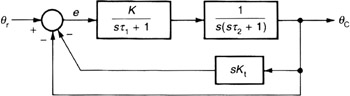 REQUIREMENT
|
|
Answers
|
| SOLUTION Since the system has a differentiating block, sK t, (which is very difficult to simulated by both analog and digital methods) the block diagram is rearranged so that this block is ahead of the integrator as follows: 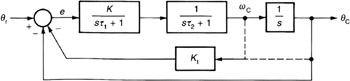
|