Introduction to Computational Fluid Dynamics
For advanced undergraduate and first year graduate students in mechanical, aerospace and chemical engineering, this textbook emphasizes understanding CFD through physical principles and examples.
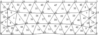
As mentioned in Section 6.1.2, a typical domain may be mapped by triangular, quadrilateral, and/or n-polygonal elements. Here, we again consider a relatively simple domain shown in Figure 6.7. The domain is mapped by triangles using ANSYS. The domain consists of two horizontal parallel plates in which a circular arc bump is provided at the bottom plate. Flow enters the left vertical boundary and leaves through the right vertical boundary.
When a domain is mapped in this way, ANSYS generates two data files:
a vertex file and
an element file.
The entries of these two files are shown in Table 6.1. They correspond to Figure 6.7. In this figure, there are 42 vertices and 59 elements. Note that the vertex numbering is completely arbitrary. The vertex file provides serial numbers of vertices along with their; x 1, x 2, and x 3 coordinates. Since the domain is two dimensional, all x 3 are zero. The element file, in contrast, provides serially numbered elements (shown inside triangles) along with the identification numbers of three vertices (since triangular elements are generated) that form the element. Like vertex numbering, element numbers are also assigned arbitrarily.
| Vertex file | Element file | ||||||
|---|---|---|---|---|---|---|---|
| NV | x 1 | x 2 | x 3 | NE | NV1 | NV2 | NV3 |
| 1 | 0.5 | 0.0 | 0.0 | 1 | 24 | 33 | 25 |
| 2 | 1.5 | 0.0 | 0.0 | 2 | 24 | 32 |