Mechanical Desktop 6 ReferencePoint Suite
Use this ReferencePoint for an overview of Mechanical Desktop 6, as well as for tips on creating components, drawing views, and other techniques.
 TABLE OF CONTENTS
 Mechanical Desktop 6 provides advanced modeling techniques, such as sweep, shell, rib, loft, bend, threads, surface cuts, and face draft, to design, create, and manipulate three-dimensional (3D) graphical objects. Mechanical Desktop 6 also provides features, such as array and mirror, to create multiple instances of graphical objects.
This ReferencePoint describes the advanced modeling features of Mechanical Desktop 6. It also explains how to manipulate 3D graphical objects using advanced modeling features.
You use the following advanced modeling features of Mechanical Desktop 6 to manipulate 3D graphical objects:
Shell: Creates hollow 3D graphical objects.
Face draft: Changes the angle of 3D graphical object s sides.
Rib: Creates a rib between two objects placed at an angle.
Sweep: Creates irregular designer models.
Bend: Creates bent objects by specifying the angle of bend.
Loft: Creates linear transitions between selected objects.
Thread: Inserts threads on standard parts.
Surface cut: Splits the surface of objects along the work plane.
You can use the sweep feature to create a designer model by defining a planar cross section along a two-dimensional (2D) or 3D path. For example, you can create an irregular designer model, such as an irregularly shaped pipe.
To create an irregularly shaped pipe:
Create a graphical object, as shown in Figure 2-1-1:
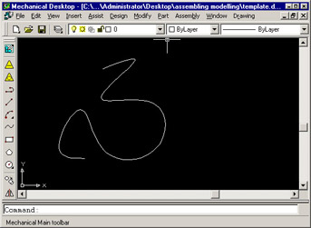
Figure 2-1-1: A Graphical Object
Select Part -> Sketch Solving -> 3D Spline Path from the main menu.
Select the spline path, as shown in Figure 2-1-2:
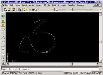
Figure 2-1-2: