Mechanical Desktop 6 ReferencePoint Suite
Use this ReferencePoint for an overview of Mechanical Desktop 6, as well as for tips on creating components, drawing views, and other techniques.
 TABLE OF CONTENTS
 An assembly in Mechanical Desktop enables you to assemble individual components of the designer model using the bottom-up or top-down approach. In the bottom-up approach, you can create the components of a designer model as individual files and assemble these files in a separate file. In the top-down approach, you can create and assemble the components of the designer models in one file.
This ReferencePoint explains how to assemble designer models in Mechanical Desktop using the bottom-up and top-down approaches.
Assemblies in Mechanical Desktop enable you to create designer models that resemble the prototype of a component. You can assemble these designer models using the 3D Constraints toolbar. To access the 3D Constraints toolbar, select View-> Toolbars-> 3D Constraints. Figure 2-2-1 shows the 3D Constraints toolbar:
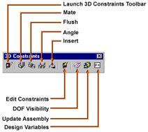
The options available in the 3D Constraints toolbar are:
Mate: Combines two surfaces placed one above the other.
Flush: Assembles two surfaces positioned parallel to each other.
Angle: Assembles a part along a specified angle.
Insert: Creates an assembly between circular objects. This option also enables you to insert a component into another component.
Edit Constraints: Modifies the constraints applied on the assembly model.
You need to create components of the assembly to assemble them in Mechanical Desktop. For example, you can create and assemble components, such as holder, shaft, bearing, and fasteners, for a roller assembly. These components are stored in a folder called bottomup.