Microstrip and Printed Antenna Design

Written for practicing engineers new to the field, this book includes a succinct treatment of wireless designs with enough detail that CAD formulas may be implemented with relative ease.
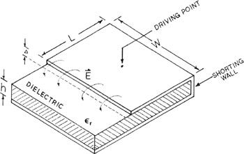
Understanding the electric field distribution under a rectangular microstrip antenna allows us to develop useful variations of the original ?/2 rectangular microstrip antenna design. In the case where a microstrip antenna is fed to excite the TM 01 mode exclusively, a virtual short circuit plane exists in the center of the antenna parallel to the x axis centered between the two radiating edges. This virtual shorting plane can be replaced with a physical metal shorting plane to create a rectangular microstrip antenna which is half of its original length (approximately ? eff/4) as illustrated in Figure 2-11. Only a single radiating edge remains with this design which reduces the radiation pattern directivity compared with a half wavelength patch. This rectangular microstrip antenna design is known as a quarter wave microstrip patch or half patch antenna. The use of a single shorting plane to create a quarter wave patch antenna was first described by Sanford and Klein in 1978 [31] Later, Post and Stephenson [32] described a transmission line model to predict the driving point impedance of a ?/4 microstrip antenna.
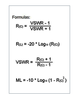
The length of a quarter wavelength patch antenna for a given operating frequency f r is:
The transmission line model of a quarter wave microstrip antenna is presented in Figure 2-12.