Microstrip and Printed Antenna Design

Written for practicing engineers new to the field, this book includes a succinct treatment of wireless designs with enough detail that CAD formulas may be implemented with relative ease.

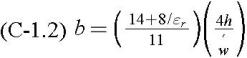
There are many approaches for developing microstrip transmission line design and analysis equations. [1] [2] [3] [4] [5] [6] [7] Relationships presented by Kajfez and Tew have proven to be very flexible for the analysis of microstrip transmission line. [8] [9] The characteristic impedance of a microstrip line is given by:
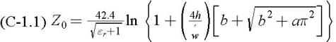
Z 0 is the characteristic impedance of the microstrip transmission line
? is the corrected transmission line width
t is the thickness of the transmission line conductor (foil thickness) see Appendix A.
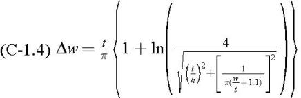
? w is the width correction factor
The use of a root finding method such as the Bisection Method (Appendix B) allows one to also use this set of equations for synthesis.
Dispersion is a very important property of microstrip lines which must be accounted for in order to expect a successful transmission line design realized using microstrip. The guide wavelength of microstrip transmission line varies with frequency:
Where ? 0 is the free space wavelength at a given frequency.
The effective dielectric constant computation is undertaken with:
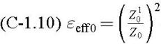
Where Z 1 0 is Z 0 computed with dielectric removed
Where Z 0 is computed with dielectric present
The computation of microstrip transmission line loss using the following relationships has the advantage that different microstrip and groundplane conductivities may be used:
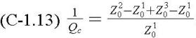
The losses are evaluated using three computations of characteristic impedance with dielectric removed, Z 1 0