Microstrip and Printed Antenna Design

Written for practicing engineers new to the field, this book includes a succinct treatment of wireless designs with enough detail that CAD formulas may be implemented with relative ease.
A single microstrip antenna utilizing an air dielectric substrate ( ? r ? 1) is able to provide a maximum gain of about 10 dBi. When larger gains are required, and a microstrip antenna solution is the best choice, a number of microstrip elements may be connected together to form an array of antennas. The array of elements provide a much larger effective aperture and therefore gain compared to a single microstrip element. This chapter will discuss elementary methods used to design microstrip antenna arrays.
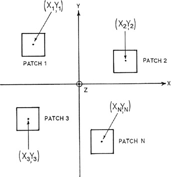
Classic linear and planar array analysis papers were presented by Elliot in the early 1960s which are very useful for the analysis of rectangular microstrip antenna arrays. [1] [2] [3] In Figure 6-1 a number of rectangular microstrip antennas are located in the x y plane. The z axis is directed out from the paper. Each microstrip antenna can be modeled as a pair of radiating slots in a groundplane. Assuming a TM 01 mode, the antennas are polarized along the y axis. A patch with its center located at ( X n, Y n) is effectively modeled as a pair of slots located at ( X n, Y n + L/2) and ( X n, Y n L/2) with identical excitation amplitude as shown in Figure 6-2.