Microstrip and Printed Antenna Design

Written for practicing engineers new to the field, this book includes a succinct treatment of wireless designs with enough detail that CAD formulas may be implemented with relative ease.
 TABLE OF CONTENTS
 The impedance bandwidth of a rectangular microstrip antenna can be determined with the total Q used in the cavity model. For a linear rectangular microstrip antenna, driven in a single mode, the normalized impedance bandwidth is related to the total Q by: [46]

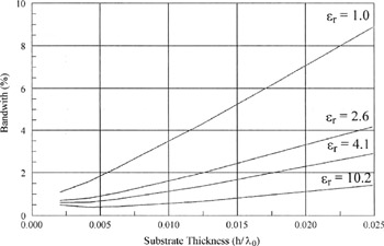
When a linear microstrip antenna design is very close to achieving an impedance bandwidth design goal, one can obtain a tiny amount of extra impedance bandwidth by designing the antenna to have a 65 ? driving point resistance at resonance rather than a perfectly matched 50 ? input resistance. The perfect match at one frequency is traded off in for a larger overall 2:1 VSWR bandwidth. [47] The impedance bandwidth also increases slightly when the width of the rectangular microstrip antenna is increased. The largest bandwidth increase occurs as the substrate dielectric constant ? r is decreased and/or the substrate thickness is increased. The affect substrate thickness and dielectric constant have on impedance bandwidth as computed with the cavity model is illustrated in Figure 2-22 for a square linearly polarized microstrip antenna.
One must recall that as the substrate thickness is increased, higher order modes provide a larger and larger contribution to an equivalent series inductance, which in turn produces a larger and larger driving point mismatch. A desirable driving...