Microstrip and Printed Antenna Design

Written for practicing engineers new to the field, this book includes a succinct treatment of wireless designs with enough detail that CAD formulas may be implemented with relative ease.
In Chapter 2 we have seen that the rectangular microstrip antenna has a number of useful designs. The circular microstrip antenna offers a number of radiation pattern options not readily implemented using a rectangular patch. The circular microstrip patch antenna's lowest mode is the TM 11 which produces a radiation pattern that is very similar to the lowest order mode of a rectangular microstrip antenna. The next higher order mode is the TM 21 which can be driven to produce circularly polarized radiation with a monopole type pattern. This is followed in frequency by the TM 02 mode which radiates a monopole pattern with linear polarization. In the late 1970s, Liquid Crystals were used to experimentally map the electric field of the driven modes surrounding a circular microstrip antenna and optimize them. [1]
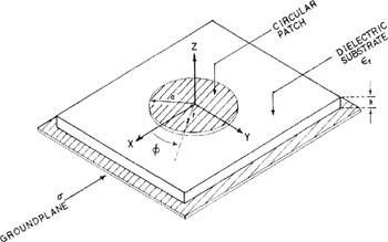
In Figure 3-1 the geometry of a circular microstrip antenna is defined. The circular metallic patch has a radius a and a driving point located at r at an angle ? measured from the ![]() axis. As with the rectangular microstrip antenna, the patch is spaced a distance h from a groundplane. A substrate of ? r separates the patch and the groundplane
axis. As with the rectangular microstrip antenna, the patch is spaced a distance h from a groundplane. A substrate of ? r separates the patch and the groundplane