As discussed in Chapter 1, the DC drive contains the components listed in Figure 4-1. A closer look will now be taken into each circuit within the DC drive unit.
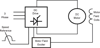 Figure 4-1: DC drive construction
 Presently, most DC drives use transistors to convert AC to DC. Historically, the most widely used method, however, is that of silicon controlled rectifiers (SCRs) in power conversion. Our focus will be on the SCR control, used in both analog and digital DC drive technology.
As recalled from Chapter 1, SCRs conduct current when a small voltage is applied to the gate circuit. Figure 4-2 illustrates this characteristic of SCRs. In Figure 4-2, the SCR is "gated on" early in the cycle, causing current flow for the remainder of the 1/2 cycle. Once the SCR goes through zero, it automatically shuts off (described as line commutation) until it is gated "on" again.
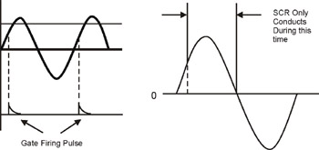 Figure 4-2: SCR controlled by a gate voltage
 Some SCR DC drives operate on a single-phase power source and use four SCRs for full-wave rectification. The focus of this section will be on the three-phase DC drives, using six SCRs for a full-wave bridge rectification. Figure 4-3 shows a typical SCR, full-wave bridge circuit, operating from three-phase line power.
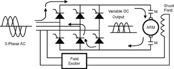 Figure 4-3: SCR full wave bridge rectification
 Though not widely used, some manufacturers replace the three SCRs on the bottom with diodes and then add a commutating diode across the DC output as a "shut off" circuit. The circuit in Figure 4-3...