Power Generation Handbook: Selection, Applications, Operation, and Maintenance

Chapter 26: FUNDAMENTALS OF ELECTRICAL SYSTEMS

CAPACITORS

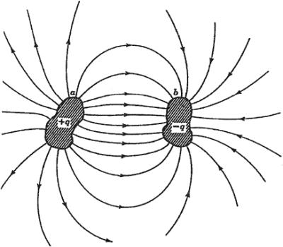
Figure 26.1 illustrates a capacitor.1 It consists of two insulated conductors, a and b. They carry equal and opposite charges, + q and ? q, respectively. All lines of force that originate on a terminate on b.The capacitor is characterized by the following parameters:


Figure 26.1: Two insulated conductors ( a and b), totally isolated from their surroundings and carrying equal and opposite charges, form a capacitor.
  • q, the magnitude of the charge on each conductor

  • V, the potential difference between the conductors

Both q and V are proportional to each other in a capacitor, or q = CV. C is the constant of proportionality. It is called the capacitance of the capacitor. C depends on the following parameters:

  • Shape of the conductors

  • Relative position of the conductors

  • Medium that separates the conductors

The unit of capacitance is the coulomb/volt or farad (F). Thus


It is important to note that:


but since


Thus,


This means that the current in a capacitor is proportional to the rate of change of the voltage with time.

In industry, the following submultiples of farad are used:

  • Microfarad ( ?F): 1 ?F = 10 ?6 F

  • Picofarad (pF): 1 pF = 10 ?12 F

Capacitors are very useful electric devices. They are used in the following applications:

  • To store energy in an electric field. The energy is stored between the conductors of the capacitors, which are normally called plates. The...

UNLIMITED FREE
ACCESS
TO THE WORLD'S BEST IDEAS

SUBMIT
Already a GlobalSpec user? Log in.

This is embarrasing...

An error occurred while processing the form. Please try again in a few minutes.

Customize Your GlobalSpec Experience

Category: LCR Meters
Finish!
Privacy Policy

This is embarrasing...

An error occurred while processing the form. Please try again in a few minutes.