Power Generation Handbook: Selection, Applications, Operation, and Maintenance

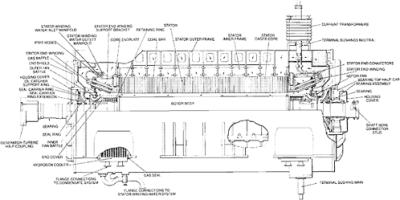
Figure 32.1 illustrates a sectional view of a large generator.1 Hydrogen is used to cool most generators having a rating larger than 50 MW.
The rotor is made from a single steel forging. The steel is vacuum-degassed to minimize the possibility of hydrogen-initiated cracking. Reheating and quenching also hardens the forging. Stress-relieving heat treatment is done following rough machining. Ultrasonic examination is performed at various stages of the rotor. Figure 32.2 illustrates the winding slots in the rotor. Figure 32.3 illustrates a rotor cross section and the gas flow.
The generator countertorque increases to 4 to 5 times the full-load torque when a short circuit occurs at the generator terminals. The rotor and turbine-end coupling must be able to withstand this peak torque.
Each winding turn is assembled separately in half-turns or in more pieces. The joints are at the centers of the end turns or at the corners. They are brazed together after assembling each turn, to form a series-connected coil. The coils are made of high-conductivity copper with a small amount of silver to improve the creep properties. The gas exits through radially aligned slots.
Slot liners of molded glass fiber insulate the coils. These separators of glass fiber are used between each turn. They insulate against almost 10 V between adjacent turns (Fig. 32.4). The end rings and end...