The Radioman's Manual of RF Devices, Principles and Practices

Dealing with the RF aspects of radio communication, this is an indispensable book for anyone involved in land mobile radio, ham radio, marine radio or aviation radio.
A piece of coaxial cable looks like a pretty boring and simple piece of wire. How much needs to be said about it? As boring and simple as a coaxial cable or transmission line might appear, it can get pretty interesting, especially when a mismatched condition exists at the load. This chapter explores transmission lines and shows how to solve many practical problems associated with transmission lines.
In a 50-ohm system, the transmitter expects to see a 50-ohm, purely resistive load. A 50-ohm transmission line terminated in a 50-ohm load will provide a 50-ohm impedance for the transmitter and efficient power transfer will occur. In Figure 10 1, a 50-ohm signal source is connected to a 50-ohm transmission line that is terminated in a purely resistive load that is, no reactance is present in the load. If the load resistor is 50 ohms, the line is matched and is nonresonant. A non-resonant line will present the proper 50-ohm system impedance to the source (transmitter) regardless of the length of the line. The impedance is 50-ohm at all points on the transmission line.
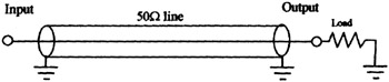
In Figure 10 1, suppose the load resistor is a pure resistance of 100 ohms. This line becomes a resonant line, the input impedance will depend upon the length of the...