Overview
From APPLIED MICROWAVE & WIRELESS, VOL. 9, NO. 4, JULY/AUGUST 1997
This article discusses third-order intermodulation distortion and the concept of third-order intercept point. Although there are other higher-order and second-order distortion products, for most systems, the higher order products are reduced in amplitude and the second-order products will be far removed and easily filtered if the incident signals are relatively close together in frequency [1], Therefore, this article focuses on third-order distortion and its associated intercept point.
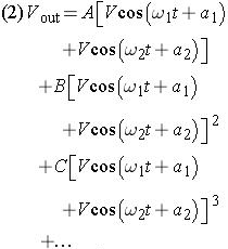
A practical amplifier will not be perfectly linear, and as such, the output will not be an exact scaled replica of the input. The resulting distorted output is a nonlinear function of the input signal and can be represented by a power series of the input voltage as follows [2]:
Let us consider the case where the input signal is made up of two signals of equal magnitude but different frequencies ( V in ? Vcos( ? 1 t+ a 1)=Vcos( ? 2 t+ a 2)). Inserting this expression for V in into the above equation gives:
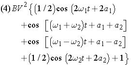
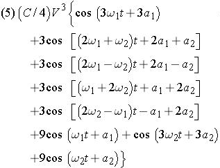
Expanding each term separately and applying some multiple-angle relations from trigonometry results in the following:
From the first power termml:
From the second power termml:
From the third power termml:
The first power term represents the linear or ideal amplifier characteristics. No new frequencies are generated and each signal applied to the...