Logic Signal Switches Information
Last revised: January 15, 2025
Logic signal switches are electronic devices which activate or deactivate a signal once an event has occurred. They are sometimes called digital signal switches, and are for the switching of digital logic signals which typically consist of high speed on/off signals. The chip is designed to pass or isolate digital signal levels but may also pass analog signals. They are a high-performance, low-power replacement for standard bus-interface devices when signal buffering is not required.
How Logic Signal Switches Work
Signals are electrical or electromagnetic means of conveying and transferring information. Logic signal switches are binary transducers, meaning they take these electrical or electromagnetic signals and convert them to binary logic (digital) signals in the form of 1s and 0s. The switching action in the device determines whether this generated signal is isolated or passed through.
Unlike normal electrical switches which physically connect or disconnect a circuit to switch between on and off, logic signal switches do not handle power. Instead, they handle logic signal levels. A binary input of 0 (false) sets the switch to "off" (open) where it operates with high resistance to create almost perfect signal isolation. A binary input of 1 (true) sets the switch to "on" (closed) where the resistance is much lower, allowing the signal to pass through. A reasonable amount of resistance, up to a few hundred ohms or so, can be tolerated in the "on" state when the signal is passed. The switch should be able to control signals at any reasonable voltage level and not be tied to ground or the positive supply.
Digital vs. Analog
Logic signal switches are considered digital switches, meaning they process digital (binary) signals. However, some digital signal switches are able to pass analog signals as well. Thus, it is important to understand and distinguish the terminology surrounding switch function.
- Digital (logic) signal switches pass or isolate digital signals. Some logic signal switches are also able to pass analog signals.
- Analog signal switches pass or isolate analog signals. Many analog signal switches can also handle digital signals.
- Bilateral switches can have one of two functions:
- They pass signals in either direction through the switch
- They can pass and isolate both analog and digital signals
- Bus switches are digital switches designed for multi-bit switching in computer applications.
Specifications
There are a number of specifications to consider when selecting logic signal switches. The most important are the number of switches, power rating, and operating temperature. Others include the maximum current rating and supply voltage.
Number of switches — the number of logic switches built into the device. This determines the number of inputs and outputs available for switching functions.
Power rating — the power required to operate the chip; also referred to as the power dissipation. It is typically expressed in watts or milliwatts. This rating is important for proper incorporation with the provisions of the rest of the system or circuit board.
Operating temperature — the ambient temperatures at which the switch is designed to operate. This is important to consider when operating in extreme temperature environments.
Maximum current rating — the maximum current that can be supplied for proper chip operation, expressed in amps (A) or milliamps (mA).
Supply voltage — the source voltage range for the device, expressed in volts (V).
Package Type
The package type affects a number of the logic signal switch's properties, including how the device is mounted on a circuit board. There a number of package types to consider.
Dual in-line packages (DIPs) can be installed either in sockets or permanently soldered into holes extending into the surface of the printed circuit board. The pins are distributed into two parallel lines along opposite site of the rectangular package. There are several types of DIP packages, such as Ceramic Dual in-line package (CDIP), Plastic Dual in-line package (PDIP), and Shrink Plastic Dual in-line package (SPDIP).
Ceramic dual in-line package (CDIP) consists of two pieces of dry pressed ceramic surrounding a "DIP formed" lead frame. The ceramic / LF / ceramic system is held together hermetically by frit glass reflowed at temperatures between 400° C to 460° C.
Plastic dual in-line package (PDIP) is widely used for low cost, hand-insertion applications including consumer products, automotive devices, logic, memory ICs, micro-controllers, logic and power ICs, video controllers commercial electronics, and telecommunications.
Small outline transistor 23 (SOT23) is a rectangular, surface mounted, small outline transistor (SOT) package with three or more gull wing leads. SOT23 features a very small footprint and is optimized for the highest possible current. Because of its low cost and low profile, SOT23 is used in home appliances, office and industrial equipment, personal computers, printers, and communication equipment.
Other typical package types for signal switches include:
- Small outline integrated controller (SOIC)
- Small outline package (SOP)
- Thin shrink small outline L-leaded packages (TSSOP)
- Quarter size outline package (QSOP)
For protection against the environment (water, dirt, dust, temperature, stress), users need to consider the strength, durability, and sealing properties of the packaging materials.
Materials
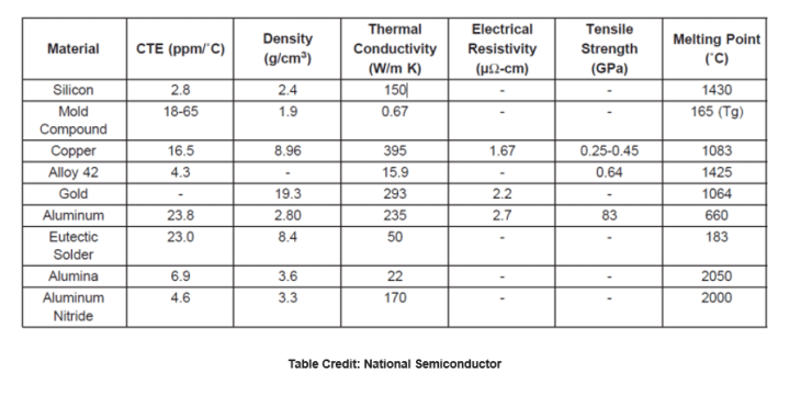
The materials used to form the semiconductor and housing play a large role in determining the properties of the device. The table below lists the properties of a number of different materials used in both packaging and connections.
Logic Signal Switches FAQs
How do logic signal switches differ in operation between digital and analog signals?
The operation of logic signal switches differs between digital and analog signals in several key ways
Signal Nature
Digital Signals: These are characterized by discrete values, typically represented by binary numbers (0s and 1s). Digital signals do not have 'in between' values and are often depicted as square waves. They are suitable for digital signal processing and allow for the transmission of more information in a smaller space.
Analog Signals: These are continuous or discrete-time signals with continuous amplitude values between a lower and upper limit. Analog signals can be continuous-time or discrete-time and are not limited to binary representation.
Switch Operation
Digital Logic Signal Switches: These switches handle logic signal levels rather than power. A binary input of 0 (false) sets the switch to "off" (open), creating high resistance and signal isolation. Conversely, a binary input of 1 (true) sets the switch to "on" (closed), allowing the signal to pass through with lower resistance.
Analog Switches: These switches are designed to handle continuous signals and may involve considerations such as ON resistance, which can affect measurement accuracy. Analog switches can have ON resistances ranging from 10 to 100 ohms, and their performance can be influenced by the signal source impedance.
Technology and Implementation
Digital Logic: Often implemented using technologies like transistor-transistor logic (TTL), complementary metal-oxide semiconductor (CMOS), and others, which are optimized for digital signal processing.
Analog Logic: May involve different logic families and technologies such as cross-bar switch technology (CBT) and gallium arsenide (GaAs), which are tailored for handling analog signals.
These differences highlight the distinct approaches required for handling digital versus analog signals in logic signal switches, reflecting the unique characteristics and requirements of each signal type.
How do logic families influence the selection of IC analog switches?
The selection of IC analog switches is influenced by the logic families used in their design and implementation. Here are some key points to consider:
Logic Families
Transistor-Transistor Logic (TTL): Uses transistors as digital switches. Variants like Fairchild advanced Schottky TTL (FAST) are also available.
Emitter Coupled Logic (ECL): Utilizes transistors to steer current through gates for computing logical functions.
Complementary Metal-Oxide Semiconductor (CMOS): Employs a combination of p-type and n-type MOSFETs to implement logic gates and other digital circuits.
Other Logic Families: Include cross-bar switch technology (CBT), gallium arsenide (GaAs), integrated injection logic (I2L), and silicon on sapphire (SOS). Gunning with transceiver logic (GTL) and gunning with transceiver logic plus (GTLP) are also options.
Selection Considerations
The choice of logic family affects the performance characteristics of the IC analog switches, such as speed, power consumption, and compatibility with other components in the system.
Different logic families offer varying levels of integration and functionality, which can influence the overall design and efficiency of the circuit.
These considerations highlight the importance of understanding the specific requirements of your application and how different logic families can meet those needs when selecting IC analog switches.
What are the technologies used in digital logic signal switches?
Digital logic signal switches utilize various technologies to manage and process digital signals effectively. Here are some key technologies used in digital logic signal switches:
Transistor-Transistor Logic (TTL)
TTL uses transistors as digital switches. It is known for its fast switching speeds, making it suitable for high-speed applications. However, TTL consumes more power as it draws current continuously, even when in a steady state.
Complementary Metal-Oxide-Semiconductor (CMOS)
CMOS technology employs a combination of p-type and n-type MOSFETs to implement logic gates and other digital circuits. It is favored for its low power consumption, as it only draws significant power during the switching process. CMOS also allows for higher integration density, enabling more transistors to be packed into a single chip.
Emitter Coupled Logic (ECL)
ECL uses transistors to steer current through gates for computing logical functions. It is known for its high-speed operation, although it typically consumes more power compared to CMOS.
Other Logic Families
Additional technologies include cross-bar switch technology (CBT), gallium arsenide (GaAs), integrated injection logic (I2L), and silicon on sapphire (SOS). These technologies offer various performance characteristics and are selected based on specific application requirements.
These technologies highlight the diverse approaches to implementing digital logic signal switches, each offering unique advantages and trade-offs depending on the application needs.
What are the advantages of using CMOS technology in digital logic signal switches?
CMOS (Complementary Metal-Oxide-Semiconductor) technology offers several advantages when used in digital logic signal switches. Here are some key benefits based on the information available:
Advantages of CMOS Technology
Low Power Consumption
CMOS technology is known for its low power consumption because it only draws significant power during the switching process. This makes it highly energy-efficient, especially suitable for battery-powered and portable devices.
High Integration Density
CMOS allows for a higher integration density, meaning more transistors can be packed into a single chip. This is beneficial for creating complex circuits on a smaller footprint, which is advantageous in modern electronic devices where space is at a premium.
Wide Voltage Range
CMOS technology offers a wider range of operating voltages, which can be advantageous in various applications requiring different voltage levels. This flexibility allows CMOS-based switches to be used in a broader range of applications.
These advantages make CMOS a popular choice for digital logic signal switches, particularly in applications where power efficiency and integration density are critical considerations.
What are the disadvantages of using CMOS technology in digital logic signal switches?
Disadvantages of Using CMOS Technology in Digital Logic Signal Switches
While CMOS (Complementary Metal-Oxide-Semiconductor) technology offers several advantages, such as low power consumption and high integration density, it also has some disadvantages when used in digital logic signal switches:
Speed
CMOS technology generally has slower switching speeds compared to other technologies like TTL (Transistor-Transistor Logic). This can be a disadvantage in applications where high-speed operation is critical.
Susceptibility to Static
CMOS devices are more sensitive to static electricity, which can damage the components if not handled properly. This makes them less robust in environments where static discharge is a concern.
What is the impact of switching speed on digital logic signal switches?
Switching speed is a critical parameter in digital logic signal switches, influencing their performance and suitability for various applications. Here are some key impacts of switching speed:
Performance and Efficiency
High-Speed Applications: Faster switching speeds are essential for applications that require rapid signal processing, such as high-frequency communication systems and fast data processing circuits. Technologies like TTL (Transistor-Transistor Logic) are known for their faster switching speeds, making them suitable for such applications.
Power Consumption: While faster switching speeds can enhance performance, they may also lead to increased power consumption. This is because more frequent switching can result in higher dynamic power usage, especially in technologies like TTL that consume power continuously.
Signal Integrity
Propagation Delay: The time it takes for a signal to travel through a switch is known as propagation delay. Faster switching speeds reduce this delay, improving the overall signal integrity and reducing the likelihood of timing errors in digital circuits.
Noise and Crosstalk: High-speed switching can introduce noise and crosstalk, which can degrade signal quality. Proper design and shielding are necessary to mitigate these effects, especially in densely packed circuits.
Technology Trade-offs
CMOS vs. TTL: CMOS technology, while offering lower power consumption and higher integration density, generally has slower switching speeds compared to TTL. This trade-off must be considered when selecting the appropriate technology for a specific application.
These impacts highlight the importance of considering switching speed in the design and selection of digital logic signal switches, balancing speed with other factors such as power consumption and signal integrity.
Logic Signal Switches Media Gallery
References
GlobalSpec—Digital Systems Design with FPGAs and CPLDs
GlobalSpec—Signal Conditioners
Overview for Switches and Multiplexers
Image credits: