Protection of Electricity Distribution Networks, 2nd Edition
5.5: Co-ordination Across Dy Transformers

5.5 Co-ordination Across Dy Transformers

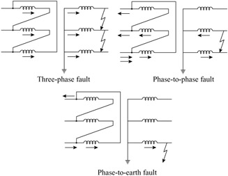
In the case of overcurrent relay co-ordination for Dy transformers the distribution of currents in these transformers should be checked for three-phase, phase-to-phase, and single-phase faults on the secondary winding, shown in Figure 5.18.


Figure 5.18: Distribution of current for a fault on a Dy transformer

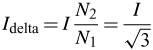
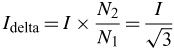
To simplify the operations, it can be assumed that the voltages between the phases of the transformer are the same, for both the primary and the secondary windings. Thus, the number of turns on the primary is equal to times the number of turns of the secondary, i.e. N 1 = N 2.

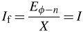
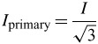
Three-Phase Fault

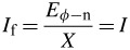
(5.8)
(5.9)
(5.10)

From the above it can be seen that the currents that flow through the relays associated with the secondary winding are equal to the currents that flow through those relays associated with the primary winding, as expected, since the primary and secondary voltages are equal and the fault involves all three phases.

Phase-to-Phase Fault

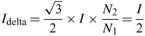
(5.11)
(5.12)
(5.13)

For this case, the current that goes through the relays installed in the secondary winding circuit is equal to times the current that flows through the relays associated with the primary on the phase that has the largest current value. From Figure 5.18 it is clear that, for this fault, the current distribution at the primary is 1-1-2, and 0-1-1 at the secondary.

Phase-to-Earth Fault

(5.14)
(5.15)
(5.16)

Thus, for a phase-to-earth fault, the current through the relays installed in the...

UNLIMITED FREE
ACCESS
TO THE WORLD'S BEST IDEAS

SUBMIT
Already a GlobalSpec user? Log in.

This is embarrasing...

An error occurred while processing the form. Please try again in a few minutes.

Customize Your GlobalSpec Experience

Category: Single Phase Transformers
Finish!
Privacy Policy

This is embarrasing...

An error occurred while processing the form. Please try again in a few minutes.