Stepping Motors: A Guide to Theory and Practice, Fourth Edition

5.2: Pull-out torque/speed characteristics for the hybrid motor

5.2 Pull-out torque/speed characteristics for the hybrid motor

5.2.1 Circuit representation of the motor

The pull-out torque is calculated by establishing a suitable model for the phase circuits and then using this model to find how the phase current varies with stepping rate.

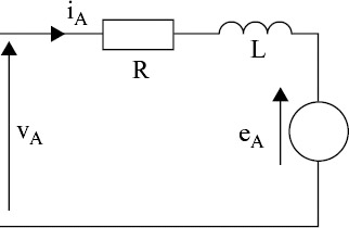
A hybrid motor has two phase windings, which are mounted on separate stator poles (Chapter 1) and therefore the phase circuit model must include the resistance and inductance of each winding. The circuit resistance is simply the sum of the forcing resistance (specified in the drive circuit design) and the winding resistance (specified by the manufacturer). In the hybrid stepping motor the inductance of the windings is almost independent of the rotor position, and the average inductance specified by the manufacturer may be used. The phase circuit model shown in Fig. 5.3 includes the total circuit resistance ( R) and the average winding inductance ( L).


Figure 5.3: Circuit model for one phase of a hybrid motor

The complete model must also take account of the voltages induced in the phase winding by rotor motion. These voltages occur because the permanent-magnet flux linking each winding varies sinusoidally with the position of the rotor. The flux linking phases A and B of a motor with p rotor teeth can be expressed as:

where ? M is the maximum flux linking each winding. When the rotor is moving at a speed d ?/ dt the induced voltages in the phase windings...

UNLIMITED FREE
ACCESS
TO THE WORLD'S BEST IDEAS

SUBMIT
Already a GlobalSpec user? Log in.

This is embarrasing...

An error occurred while processing the form. Please try again in a few minutes.

Customize Your GlobalSpec Experience

Category: Stepper Motors (rotary)
Finish!
Privacy Policy

This is embarrasing...

An error occurred while processing the form. Please try again in a few minutes.