Stepping Motors: A Guide to Theory and Practice, Fourth Edition
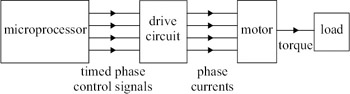
The initial stages of system design are concerned with steady-state performance; the choice of stepping motor and drive circuit is mainly dictated by the maximum tolerable position error and the maximum required stepping rate. When this task of selection is completed, the designer must consider how the motor and drive are to be controlled and interfaced to the remainder of the system. The aim of the following chapters, therefore, is to show that system performance can be maximised and costs minimised by correct choice of control scheme and interfacing technique.
The open-loop control schemes discussed in this chapter have the merits of simplicity and consequent low cost. A block diagram for a typical open-loop control system is shown in Fig. 6.1. Digital phase control signals are generated by the microprocessor and amplified by the drive circuit before being applied to the motor. Although the system illustrated receives its phase control signals from a microprocessor a number of alternatives are presented later in this chapter.
Whatever the signal source, the designer needs to know what restrictions are imposed on the timing of the control signals by the parameters of the drive, motor and load. Some of these restrictions stem from the steady-state performance (e.g. the maximum stepping rate with a given load torque can be deduced from the pullout torque/speed characteristics), but still more restrictions arise when transient performance is considered. If the system has a high inertia, for example, the maximum stepping rate...