Band-rejection filters are very similar in design approach to the bandpass filter of the last section. Only, in this case, we want to reject a certain group of frequencies as shown by the curves in Fig. 3-30.
The band-reject filter lends itself well to the low-pass prototype design approach using the same procedures as were used for the bandpass design. First, define the bandstop requirements in terms of the low-pass attenuation curves. This is done by using the inverse of Equation 3-14. Thus, referring to Fig. 3-30, we have:
This sets the attenuation characteristic that is needed and allows you to read directly off the low-pass attenuation curves by substituting BW c/ BW for f c/ f on the normalized frequency axis. Once the number of elements that are required in the low-pass prototype circuit is determined, the low-pass network is transformed into a band-reject configuration as follows:
Each shunt element in the low-pass prototype circuit is replaced by a shunt series-resonant circuit, and each series-element is replaced by a series parallel-resonant circuit.
This is shown in Fig. 3-31. Note that both elements in each of the resonant circuits have the same normalized value.
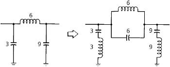 FIG. 3-31: Low-pass to band-reject transformation.
 Once the prototype circuit has been transformed into its band-reject configuration, it is then scaled in impedance and frequency using the following formulas. For all series-resonant circuits:
For all parallel-resonant circuits:
where, in all cases,