Mechanics of Composite Materials with MATLAB
Written specifically for students in engineering and materials science, this text places emphasis on learning the composite material mechanics computations and on understanding the underlying concepts.
In Chap. 7, we derived the necessary formulas to calculate the strains and stresses through the thickness and the force and moment resultants given the strains and curvatures at a point ( x, y) on the reference surface. In this chapter, we will study the reverse process. Given the force and moment resultants, we want to calculate the stresses and strains through the thickness as well as the strains and curvatures on the reference surface. We also want to do this by computing the laminate stiffness matrix.
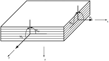
Figures 8.1 and 8.2 show the force and moment resultants, respectively. In the two figures, a small element of laminate surrounding a point ( x, y) on the geometric midplane is shown [1].
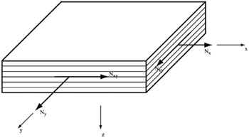
The force resultants N x, N y, and N xy can be shown to be related to the strains and curvatures at the reference surface by the following equation:
| (8.1) | |
Similarly, the moment resultants M x, M y, and M xy can also be shown to be related to the strains and curvatures at the reference surface by the following equation:
| (8.2) | |
where the matrix components A ij, B ij, and D ij are given as follows:
| (8.3) | 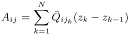 |
| (8.4) | 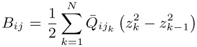 |
| (8.5) | 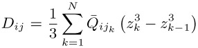 |
Equations (8.1) and (8.2) can be combined into one single...