Biomechanics: Concepts and Computation

Using a quantitative biomechanics approach, this book integrates both general and specific topics, theoretical background and biomedical engineering applications, as well as analytical and numerical approaches.
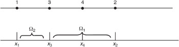
The objective of a finite element program is, to compute the coefficient matrix K and the right-hand side array  and eventually to solve the resulting system of equations taking the boundary conditions into account. To illustrate the typical data structure and the layout of a finite element program, consider, as an example, the mesh depicted in Fig. 14.8.
The MATLAB programming language is used for explanation purposes. The following data input is needed:
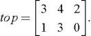
Element topology First of all the domain is divided into a number of elements and each node is given a unique global number. In this example two elements have been used, the first element ? 1 is a quadratic element connecting nodes 3, 4 and 2 (in that order) and the second element is a linear element having nodes 1 and 3 (again, in that order). The node numbers of each element are stored in the topology array top,such that the i-th row of this array corresponds to the i-th element. In the current example the topology array would be:
Besides the node numbers of the element, a number of identifiers may be included for each element, for instance to refer to different material parameters c or different element types, e.g. linear versus quadratic elements. In fact, the MATLAB code provided to experiment...

 TABLE OF CONTENTS