Die Design Fundamentals, 3rd Edition

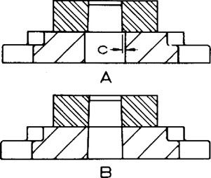
Machining holes for the passage of slugs. There are two methods of applying holes in the die holder for the passage of slugs (Figure 17.24). In view A, slug relief holes are machined with straight walls. Dimension C is 1/16 inch (1.6 mm) for blanks up to No. 16 gage (0.0625 in. or 1.6 mm), and proportionately more for thicker blanks.
The method shown in view B is preferred for blanking and piercing soft materials, which have a tendency to stick together and form thick slugs that could jam. The holes in the die set are die-filed to the same angle applied to the die block for relief.
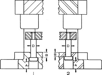
Stripper bolt holes. Counterbored holes for stripper bolts should be proportioned carefully because considerable pounding occurs against the bottoms of the counterbores in operation of the die. Also, a spring stripper may occasionally stick or become jammed. When this happens, a pry bar is used to free it. The stripper then slams up with all the stored energy in the springs. Apply the following minimum proportions (Figure 17.25):
| dimension A | = strip thickness + grinding allowance. |
| dimension B | = D for a semi-steel die set, and 3/4 D for a steel die set. |
Projections. All projections in a die block (Figure 17.26) must be supported by corresponding projections applied...