9.5 QMF Filter Banks
One of the earliest proposed approaches for the design of 2-band filter banks is the so-called quadrature mirror filter (QMF) bank (Croisier et al., 1976), where the analysis highpass filter is designed to alternate the signs of the impulse-response samples of the lowpass filter, that is
| (9.53) | 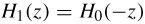
|
Please note that it is assumed the filters have real coefficients. For this choice of the analysis filter bank, the magnitude response of the highpass filter, H 1( e j?), is the mirror image of the lowpass filter magnitude response, H 0(e j ?), with respect to the quadrature frequency  . Hence the QMF nomenclature.
The 2-band filter bank illustrated in Figure 9.19 and discussed in Section 9.4 can also be analyzed in the following way. The signals after the analysis filter are described by
| (9.54) | 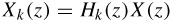
|
for k = 0, 1. The decimated signals are
| (9.55) | 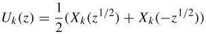
|
for k = 0, 1, whereas the signals after the interpolator are
| (9.56) | 
|
Then, the reconstructed signal is represented as
| (9.57) | 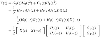
|
The last equality is the so-called modulation-matrix representation of a 2-band filter bank. The aliasing effect is represented by the terms containing X(- z). A possible solution to avoid aliasing is to choose the synthesis filters such that
| (9.58) | 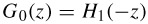
|
| (9.59) | 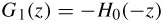
|
This choice keeps the filters G 0( z) and G 1( z) as lowpass and highpass filters, respectively, as desired. Also, the aliasing is now canceled by the...