Dynamics of Multibody Systems, Third Edition

5.7: APPLICATION TO A MULTIBODY SYSTEM

5.7 APPLICATION TO A MULTIBODY SYSTEM

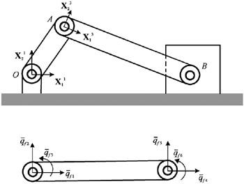
The planar slider crank mechanism shown in Fig. 7 consists of four bodies: the fixed link (ground), denoted as body 1, the crankshaft OA (body 2), the connecting rod AB (body 3), and the slider block (body 4) at B. All bodies are assumed to be rigid except the flexible connecting rod AB, which has length l, mass density ?, and modulus of elasticity E. The connecting rod AB is connected to the crankshaft and the slider block by means of revolute joints. For simplicity, the superscript that indicates the body number will be omitted in the discussion that follows with the understanding that all vectors and matrices are associated with the deformable connecting rod.


Figure 5.7: Planar slider crank mechanism.

Assumed Displacement Field

The displacement field of the connecting rod is assumed to be


where u f = [ u f 1 u f 2] T is the displacement vector, S b is the shape matrix defined as


? = ( x/ l), and the vector of elastic coordinates q f is


in which q f 1 and q f 4 are the axial displacements of the endpoints, q f 2 and q f 5 are the transverse displacements of the endpoints, and q f 3 and q f 6 are the slopes at the endpoints. One may observe that the...

UNLIMITED FREE
ACCESS
TO THE WORLD'S BEST IDEAS

SUBMIT
Already a GlobalSpec user? Log in.

This is embarrasing...

An error occurred while processing the form. Please try again in a few minutes.

Customize Your GlobalSpec Experience

Category: Linear Potentiometers
Finish!
Privacy Policy

This is embarrasing...

An error occurred while processing the form. Please try again in a few minutes.