Electrical Power Systems Quality, Second Edition

This book provides a non-mathematical guide to basic power-quality strategies and methods used to protect electronic systems.
This section illustrates a procedure for designing harmonic filters for industrial applications. This procedure can also be used to convert an existing power factor correction capacitor into a harmonic filter. As described in Sec. 4.1.2, power factor correction capacitors are used widely in industrial facilities to lower losses and utility bills by improving power factor. On the other hand, power factor correction capacitors may produce harmonic resonance and magnify utility capacitor-switching transients. Therefore, it is often desirable to implement one or more capacitor banks in a facility as a harmonic filter.
Filter design procedures are detailed in the steps shown below. The best way to illustrate the design procedures is through an example.
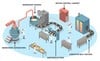
A single-tuned notch filter will be designed for an industrial facility and applied at a 480-V bus. The load where the filter will be installed is approximately 1200 kVA with a relatively poor displacement power factor of 0.75 lagging. The total harmonic current produced by this load is approximately 30 percent of the fundamental current, with a maximum of 25 percent fifth harmonic. The facility is supplied by a 1500-kVA transformer with 6.0 percent of impedance. The fifth-harmonic background voltage distortion on the utility side of the transformer is 1.0 percent of the fundamental when there is no load. Figure 6.7 shown earlier depicts the industrial facility where the filter will be applied. The harmonic design procedures are provided in the following steps.
1. Select a tuned frequency for the...