Error-Control Block Codes for Communications Engineers
An engineer s guide to the theory behind the common random-error-control block codes, and their applications in digital communications.
We have seen that in classical digital communication systems with coding, the channel encoder and the modulator design are considered as separate entities. This is shown in Figure 7.1.
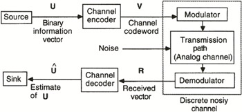
The modem (modulator-demodulator) transforms the analog channel into a discrete channel and the channel codec (encoder-decoder) corrects errors that may appear on the channel. The ability to detect or correct errors is achieved by adding redundancy to the information bits. Due to channel coding, the effective information rate for a given transmission rate at the encoder output is reduced.
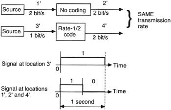
It can be seen from Figure 7.2 that the information rate with channel coding is reduced for the same transmission rate at locations 2? and 4?. If we increase the information rate with coding from 1 bps to 2 bps, the transmission rate at the encoder output increases to 4 bps.
In modem design, we can employ bandwidth efficient multilevel modulation to increase spectral efficiency. For 2 ?-ary modulation, ? number of bits are used to specify a signal symbol which, in turn, selects a signal waveform for transmission. If the signaling interval is T seconds, the symbol rate is 1/ T symbol/s and the transmission rate at the input of the modulator is ?/ T bps. Also, the signal bandwidth is inversely proportional to the signaling interval if the carrier signal frequency f