High Performance ASIC Design: Using Synthesizable Domino Logic in an ASIC Flow

4.2: Unate Transform

4.2 Unate Transform

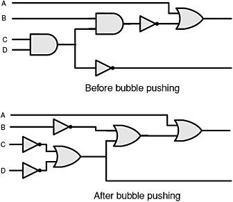
Since domino logic cells cannot have inverters or inverting logic present, all such inversions need to be moved to the primary inputs or outputs of the domino logic module. For a logic block with multiple pipeline stages, the inverters can also be incorporated into flip-flops driving the logic. The actual movement of inverters through logic can be achieved by the recursive application of De Morgan s law [2]. Since inverters are schematically represented in logic as bubbles, the unating process by which inverters are moved to the inputs of the module is also called bubble pushing. In Figure 4.3 a circuit is shown before and after bubble pushing. The initial circuit is seen to have inverters between logic cells. After bubble pushing, all the inverters are placed at the inputs of the circuit. At this point they can be easily incorporated into domino-compatible flip-flops driving the logic.


Figure 4.3: Removing an inverter with bubble pushing.

Unfortunately, it is not possible to always push inverters to the inputs of the block. Under those circumstances it may be possible to remove the inverters by pushing them forward to the outputs of the module [2]. This is not possible when an inverted and uninverted form of the signal is part of some reconvergent logic. When this occurs the inverter is considered to be trapped. To remove trapped inverters one must duplicate the logic cone from the trapped inverter to its primary inputs [2]. The overhead in...

UNLIMITED FREE
ACCESS
TO THE WORLD'S BEST IDEAS

SUBMIT
Already a GlobalSpec user? Log in.

This is embarrasing...

An error occurred while processing the form. Please try again in a few minutes.

Customize Your GlobalSpec Experience

Category: Logic Gates
Finish!
Privacy Policy

This is embarrasing...

An error occurred while processing the form. Please try again in a few minutes.