High-Speed Circuit Board Signal Integrity

Filled with on-the-job-proven examples, this hands-on reference offers you the knowledge needed to quickly pinpoint transmission problems that can compromise your entire circuit design.
 TABLE OF CONTENTS
 The focus of previous chapters has been on the characteristics of single lines, with only casual mention of coupled lines. This chapter discusses the way transmission lines couple to each other and so induce noise voltages to other signal lines, and the effect they have on one another's impedance and timing.
Two side-by-side microstrips (traces "E1" and "E2") are shown in Figure 8.1. If the lines are close enough, the magnetic and electric fields will encompass both traces, allowing each trace to influence the other. As circuit elements, the magnetic coupling is represented by a mutual inductance L 12, while the electric coupling is represented by the mutual capacitance C 12.
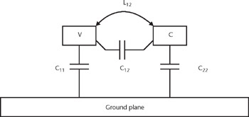
The undesirable coupling of energy from a switching line (the culprit)toapassive line (the victim) is called crosstalk (also sometimes called cross coupling). This is what often first comes to mind when designers consider closely spaced traces running parallel to each other. A switching culprit line inducing noise voltage on a passive (unswitched) victim is discussed in Section 8.5.
A second case requiring analysis occurs when all of the signals in a closely spaced group (such as a wide data bus) switch simultaneously, with none being passive. The switching pattern of these signals results in a change of impedance (and, at least in microstrip, a change in the time of flight as well) of these signals.
Although this behavior is a result of coupling between traces...