High-Speed Circuit Board Signal Integrity
Filled with on-the-job-proven examples, this hands-on reference offers you the knowledge needed to quickly pinpoint transmission problems that can compromise your entire circuit design.
Two transmission lines are shown linked by mutual inductance and capacitance in Figure 8.2. Both traces are driven by identical pulse generators (PG1 and PG2) having a fixed output impedance of R g and are terminated in load resistors R L such that reflections are not created when the launched waves reach the far end.
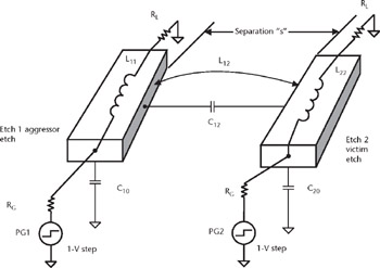
The pulse generators may either drive the lines in the same direction (i.e., in phase with one another) or in opposite directions (180 o out of phase). The case where only one line switches while the other remains static is the crosstalk case discussed in Section 8.5.
Signals switching in the same direction and carrying the same current are called even mode signals because the electric field lines are symmetrically arraigned about an axis of symmetry [1], as shown for a microstrip in Figure 8.3. Stripline exhibits the same behavior but with the electric fields terminating on both plates.
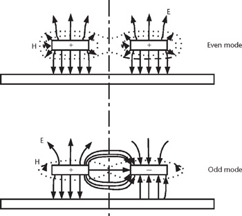
When switching in opposite direction ( odd mode), the electric field lines no longer exhibit this symmetry (although, as shown, the magnetic fields do).
The behavior of coupling capacitance appearing between traces was examined in Chapter 3. The influence of mutual capacitance on a circuit was shown in Examples 3.3 and 3.4 to depend on the switching activity occurring...