High-Speed Circuit Board Signal Integrity

Filled with on-the-job-proven examples, this hands-on reference offers you the knowledge needed to quickly pinpoint transmission problems that can compromise your entire circuit design.
If strong enough, crosstalk the undesired coupling of energy from one or more culprit lines to one or more victim lines causes receiver noise margins to be reduced, thereby rendering a circuit susceptible to false triggering. Crosstalk-related problems can be particularly vexing to debug, especially if the circuits only fail occasionally.
A typical situation is shown in Figure 8.19. A clock sent between ASICs is routed adjacent to a data line with a spacing s = 4 mils for a distance of 12 in. The routing layer is 1-oz copper and is specified by the PWB vendor to have a 63- ? impedance (i.e., a line taken in isolation will have Z o = 63 ?) when the trace is 4 mils wide.
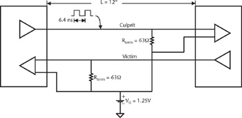
The victim data line is asserted low by its driver (which is series terminated and has an output impedance of 63 ?), and likewise is terminated to V tt at its far end in 63 ?.
Coupling from the culprit to victim line causes noise pulses (crosstalk) to appear at both ends of the victim line. It's evident from the simulation results presented in Figure 8.20 that the coupling is strong and furthermore that the forward crosstalk pulse in this text called far-end crosstalk (FEXT) has different characteristics than the crosstalk pulse traveling back to the load near-end crosstalk (NEXT).
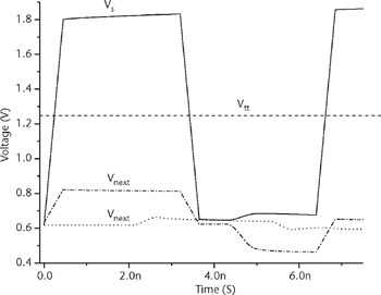
In this example, the NEXT and FEXT pulses are...